
This is where smart‐grid technology comes into play. During peak energy use or when wind and solar contributions are low, stored energy is added to help stabilize the grid in the form of 32 inch diameter carbon fiber composite flywheels similar to the one shown in Figure 2 below from Beacon Power, LLC in Tyngsboro, MA.
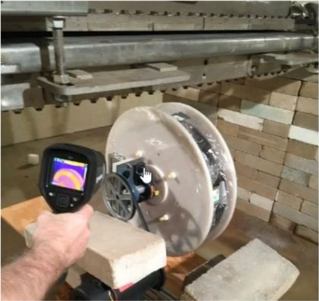
Figure 2
Beacon’s flywheel is essentially a mechanical battery that stores kinetic energy in a rotating mass. Advanced power electronics and a motor/generator convert that kinetic energy to electric energy, making it instantly available when needed. However, to do so these flywheels must be turning 24 hours a day, 7 days a week. Conventional metal flywheels would crack and fail under these conditions so carbon composite materials are used instead. 200 of these flywheels are located at one Stephentown, New York facility providing 20 MW of electricity to the grid instantly when needed.
So what’s the problem you might ask? These carbon composite flywheels are manufactured from thousands of strands of carbon fibers soaked in a polymer resin and then wound tightly onto a core. Each core is then baked at 200 degrees continuously for about a week to completely cure the 7 inch thick core using technology that has not changed in past 50 years!
MAS Automation Systems is working on research funded by the DOE (Department of Energy) to develop technology that would allow carbon composite flywheels of similar size and specifications to be cured within 45 minutes using high energy – a 4 million electron volt beam/x‐ray!
Figure 3 shows the carbon fiber tow line (foreground) being fed into the “slurry” where it is coated with a proprietary formula of polymer resin. The tow line itself is a ribbon composed of 3,000 carbon fiber strands (about 0.15 x 0.17 inches).
Once coated, the carbon fiber tow line is then wound onto a spool shown in the background containing internal components designed to exert pressure from the inside out, forcing as much excess resin out of the carbon fibers as possible. The slurry assembly along with the internal components of the spool were manufactured from toolpaths generated using VisualMILL.
Figure 4 shows a carbon composite flywheel sample being positioned under a 4 million electron volt beam (called an E‐Beam Accelerator) that is focused into an x‐ray at the top of the spool (at the white arrow) while the spool is slowly related. The E‐Beam Accelerator, owned by IBA and located on New York’s Long Island is 3 stories tall with the bottom portion shown here in a room whose lead filled walls are 3 feet thick! Figure 5 shows a scale model of the E‐Beam Accelerator, courtesy of IBA.
While the electron beam itself only penetrates ¼ inch into the carbon composite flywheel, the x‐ray provides complete penetration and curing of the sample within 45 minutes of exposure. The heat radiating from the flywheel sample can be seen on the hand help meter in Figure 1 above. Using the conventional baking method the same sample size would take about 12 hours to cure.
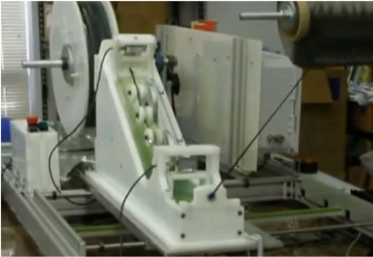
Figure 3

Figure 4
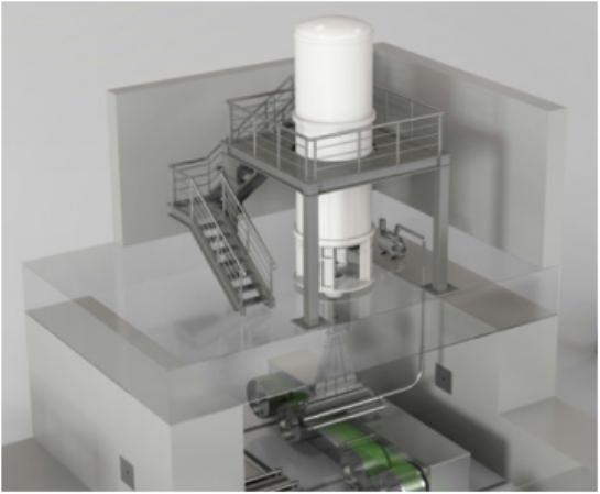
Figure 5
Since 2009, MAS has been using VisualMILL to assist them in manufacturing components for use in their automation systems integration projects including the carbon composite flywheel research mentioned above. Mark Sherwin, president of MAS Automation Systems has a background in electronics and is a Control Engineer. Mark initially chose VisualMILL because of its ability to generate toolpaths from geometry files created in their Geomagic Design® CAD software. Moving forward, Mark stayed with VisualMILL because if its reliability, ease of use and technical support. Figure 6 and Figure 7 below show components from the slurry and flywheel assemblies seen in Figure 3 above after programming and simulating 2 and 3 axis toolpaths in VisualMILL.
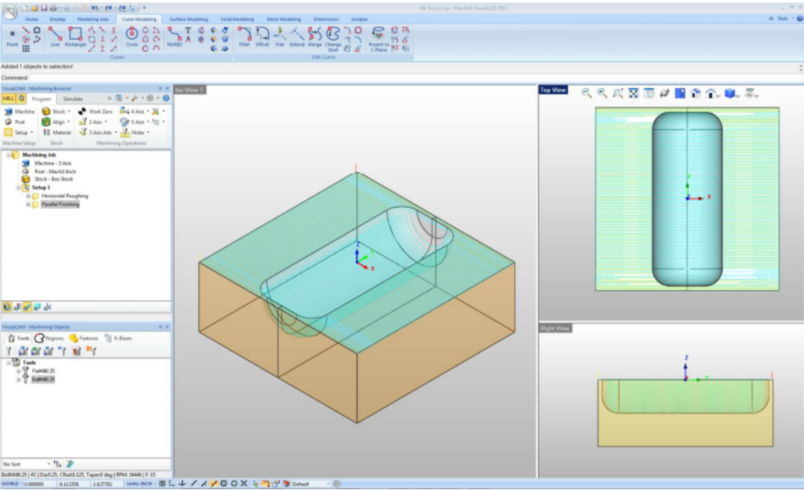
Figure 6
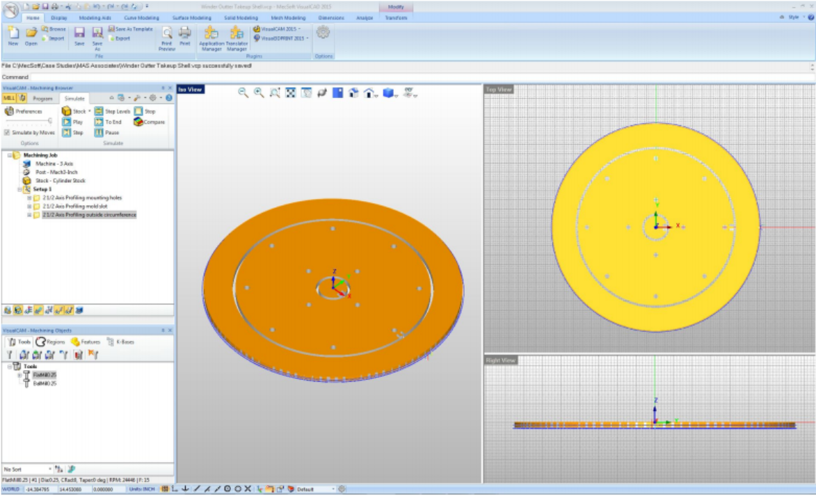
Figure 7
MAS also used VisualMILL to machine components for its Sherloc™ Pressure Testing Work Cell (shown in Figure 8) that is compliant with Pipeline Hazardous Materials Safety Administration, DOT P173.28. The pressure testing work cells developed by MAS have performed over 300,000 test cycles in the field with one chemical spill.
The removable EPDM Foam Test Heads were machined using 2.5 axis toolpaths generated with VisualMILL shown in Figure 9 below.
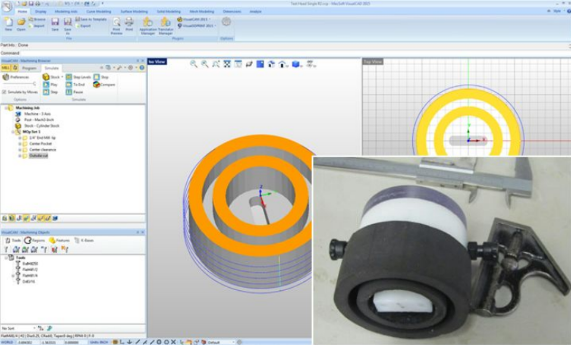
Figure 9 – The actual test head for the Sherloc™ Pressure Testing Work Cell is shown (inset) along with the VisualMILL part file containing the toolpaths.